FM Transmission Towers: The High Ground of Broadcasting
What Is an FM Transmission Tower?
AYBERK BLOG
FM Transmission Towers: The High Ground of Broadcasting
Radio broadcasting remains one of the most effective means of reaching wide audiences. For a transmission to be clear, stable, and far-reaching, it must rely on solid infrastructure. At the heart of this system lies the FM transmitter—but equally important is the structure that lifts the signal into the air: the FM transmission tower. In this article, we’ll explore the components, engineering details, antenna systems, and RF measurement principles involved in FM transmission towers.
1. What Is an FM Transmission Tower?
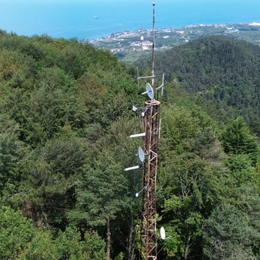
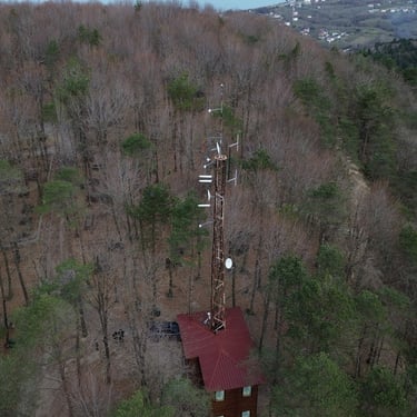
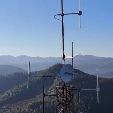
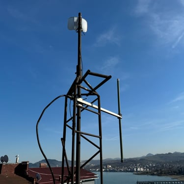
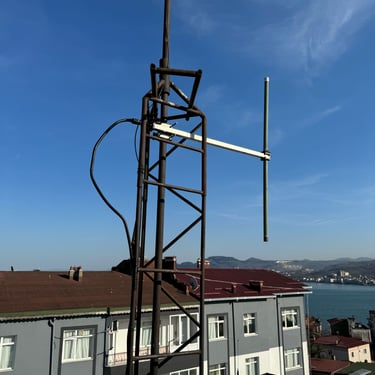
An FM transmission tower is a tall structure designed to mount FM antennas at an elevated height to maximize their broadcast range. Since FM signals travel in a line-of-sight path, elevating the antenna is crucial to overcome terrain and obstacles.
2. Tower Structure and Components
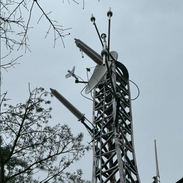
📡 Antenna System
FM antennas operate in the 87.5–108 MHz band and are usually omnidirectional (360° coverage) or directional (focused coverage). The choice depends on the target audience area.
Common FM antenna types:
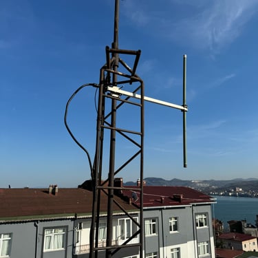
Dipole antennas (single or stacked)
Yagi-Uda antennas (for directional coverage)
Circularly polarized antennas
Panel or slot antennas
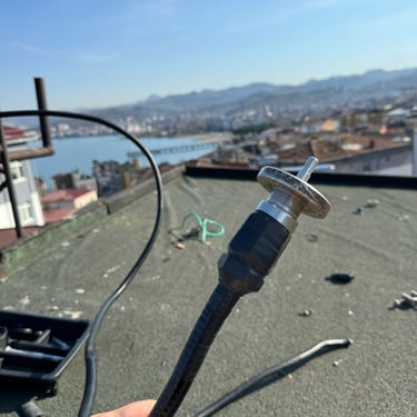
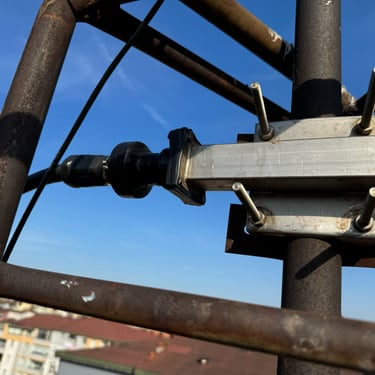
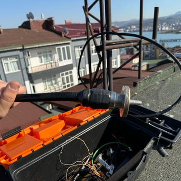
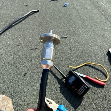
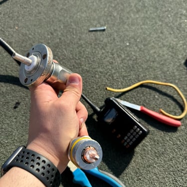
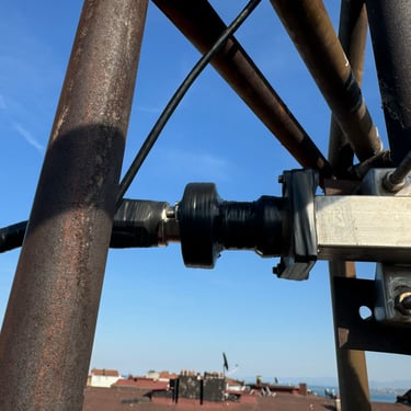
🔗 Feeder Line
The RF signal travels from the transmitter to the antenna via coaxial cable or, in high-power applications, waveguides. The cable must have:
Low attenuation at FM frequencies
High shielding effectiveness
Excellent VSWR performance
Examples: Andrew Heliax LDF4-50A, RFS CELLFLEX, etc.
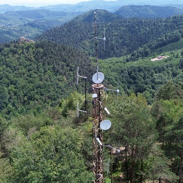
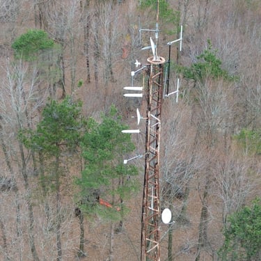
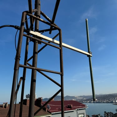
🏗️ Tower Types
Lattice Towers (triangular/square): Durable, wind-resistant, and easy to climb.
Monopole Towers: Single-tube designs, more aesthetic but limited in load capacity.
3. Antenna Height and Broadcast Engineering
The effective range of an FM broadcast heavily depends on the antenna’s height above average terrain (HAAT).
Coverage radius estimation:
📐 Coverage radius (km) ≈ 3.57 × √antenna height (m)
A 100-meter-high antenna can cover a 35–50 km radius under ideal conditions.
4. Key Technical Parameters
🧮 ERP (Effective Radiated Power)
ERP represents the effective output power considering antenna gain and system losses:
ERP (dBW) = Transmitter Power (dBW) + Antenna Gain (dBd) – System Loss (dB)
Regulatory bodies (like RTÜK/BTK in Turkey or the FCC in the US) limit ERP to prevent interference.
📉 VSWR (Voltage Standing Wave Ratio)
VSWR indicates how efficiently RF energy is delivered to the antenna. Ideal VSWR is 1.0:1; practical values should be under 1.3:1. A high VSWR may damage the transmitter or cause performance loss.
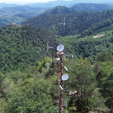
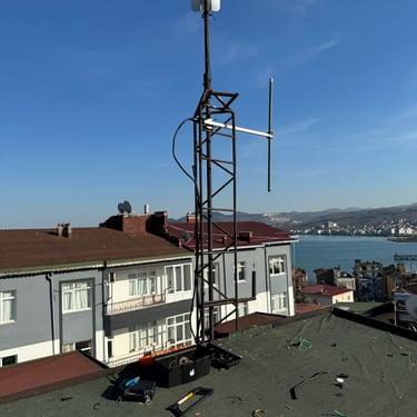
5. Tower Site Planning
Choosing the right site for an FM tower involves more than just height:
Elevation: Higher ground improves signal propagation.
Terrain: Hills, valleys, or water bodies affect signal behavior.
Infrastructure: Power, internet, and road access must be available.
EMI Conditions: The area should be free of strong electromagnetic interference.
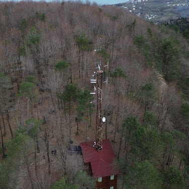
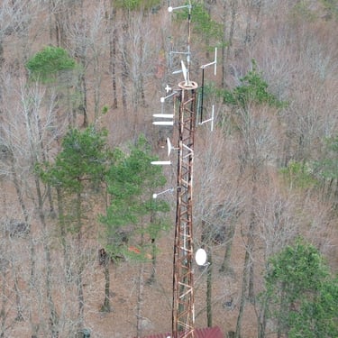
6. Shared Use and Multi-Channel Systems
A single FM tower can host multiple stations:
Each antenna is installed at a different height and orientation.
Combiners allow multiple transmitters to share one antenna.
Filters and isolators prevent intermodulation or interference.
This shared model reduces infrastructure costs and simplifies maintenance.
7. Maintenance and Safety
FM towers require routine inspections at least once a year:
Mechanical checks: Rust, bolts, structural integrity
Grounding: Ensure proper lightning protection
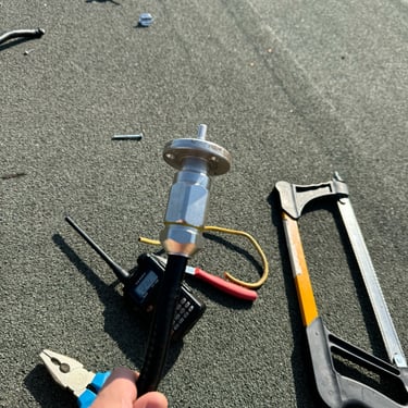
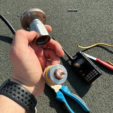
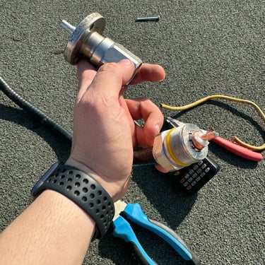
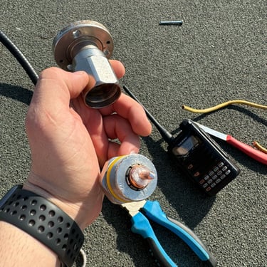
Antenna system: Measure VSWR, check connectors and cables
Warning lights: Must meet aviation safety standards (e.g., ICAO)
Climbing safety: Technicians must use personal protective equipment—harnesses, helmets, climbing ropes—according to occupational safety rules.
8. Conclusion
FM transmission towers are critical to reliable radio broadcasting. With proper engineering, regular maintenance, and precise RF planning, these structures enable millions to receive clear and consistent audio content.
👨🔧 Bonus: Recommended RF Test Equipment
Bird 43 Wattmeter – For measuring forward and reflected power
Rigol DSA815-TG – Affordable spectrum analyzer
Rohde & Schwarz ZVL – Vector network analyzer for professional antenna tests
SWR/Power Meters – Portable models from MFJ, Diamond, Nissei, etc.