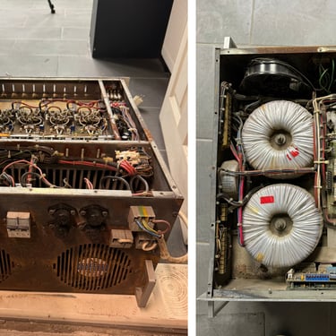
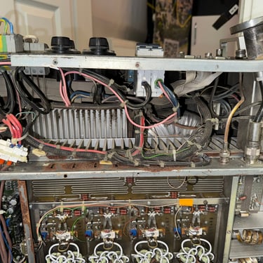
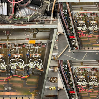
📡 RF Power Amplifiers
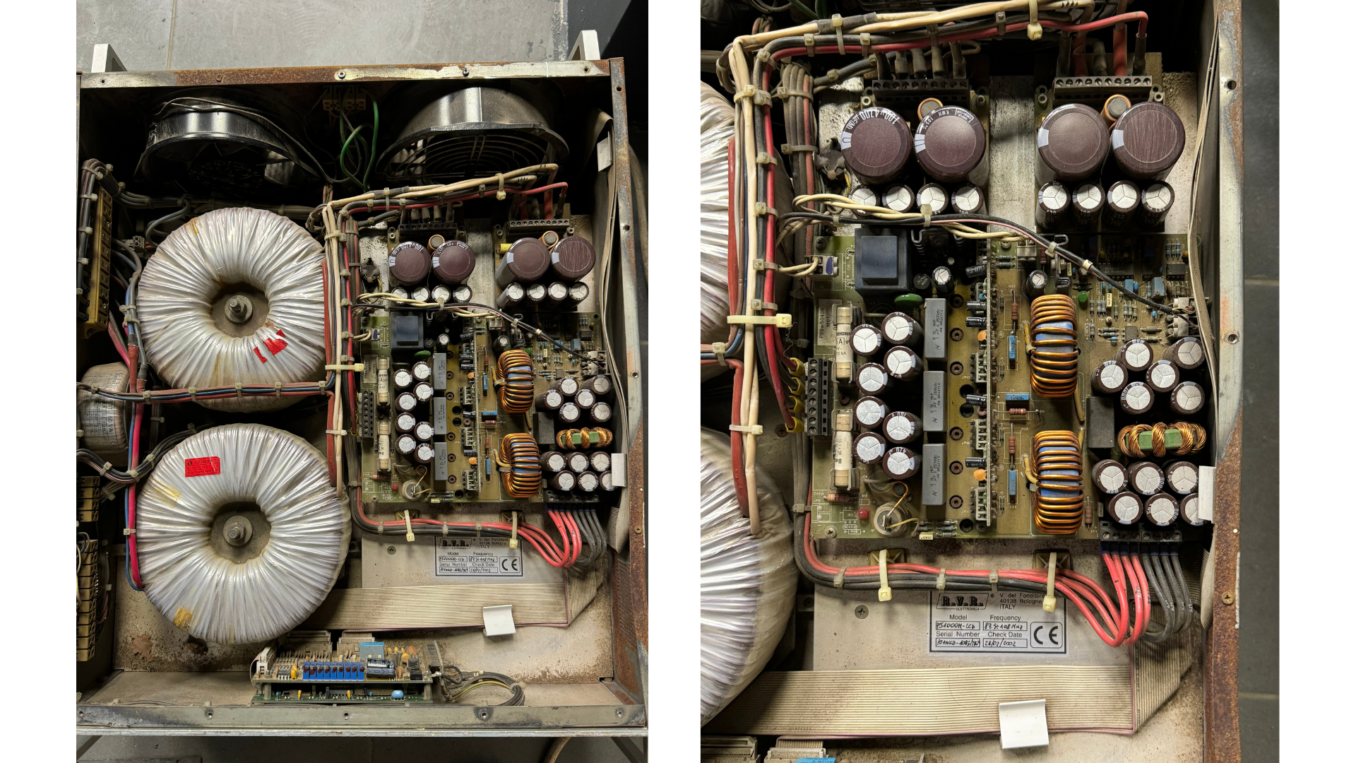
RF (Radio Frequency) power amplifiers are electronic circuits used to increase the power level of radio frequency signals. They are essential components in communication systems, including broadcasting (FM/AM), satellite communication, radar, wireless networks, and mobile telecommunications. Their primary role is to take a low-level RF input signal and amplify it without distorting its original waveform.
AYBERK BLOG
G1. Introduction
RF (Radio Frequency) power amplifiers are electronic circuits used to increase the power level of radio frequency signals. They are essential components in communication systems, including broadcasting (FM/AM), satellite communication, radar, wireless networks, and mobile telecommunications. Their primary role is to take a low-level RF input signal and amplify it without distorting its original waveform.
2. Operating Principle
An RF amplifier boosts the amplitude of a signal within a specific frequency range. Unlike audio amplifiers, which operate in kHz ranges, RF amplifiers work in the MHz to GHz spectrum. The amplifier must maintain the integrity of the input signal's frequency while increasing its power level.
An RF amplifier typically consists of three main stages:
Input Matching Network – Matches the source impedance (usually 50 ohms) to the input of the amplifier.
Gain Stage – The core amplification is done here using transistors or integrated RF chips.
Output Matching Network – Ensures maximum power transfer to the load (antenna, filter, etc.) by matching impedances.
3. Types of RF Amplifiers
RF amplifiers come in various types depending on their intended application:
3.1 Low Noise Amplifier (LNA)
Used at the front-end of receivers.
Amplifies weak signals with minimal additional noise.
3.2 Power Amplifier (PA)
Used at the output of transmitters.
Delivers high power (from 1 W to several kW) to the antenna.
3.3 Wideband RF Amplifier
Operates across broad frequency ranges.
Common in test equipment and military receivers.
3.4 Narrowband RF Amplifier
Optimized for a specific frequency.
High efficiency and low spurious emissions.
4. Common Active Devices
RF amplifiers use various types of active components depending on power and frequency requirements:
BJT (Bipolar Junction Transistors)
MOSFET (Metal Oxide Semiconductor Field Effect Transistors)
LDMOS (Laterally Diffused MOSFET) – Ideal for high-power RF applications.
GaN (Gallium Nitride) Transistors – Offer high efficiency, high voltage handling, and excellent thermal performance.
5. Key Design Parameters
When designing or selecting an RF amplifier, several critical specifications must be considered:
Gain: Ratio of output to input power (in dB).
Bandwidth: Range of frequencies over which the amplifier maintains performance.
Noise Figure (NF): Amount of noise added by the amplifier (important in receivers).
Efficiency: Ratio of RF output power to total power consumed.
IP3 (Third-order Intercept Point): A measure of linearity; higher is better.
SWR / VSWR: Reflects impedance matching with the load.
Output Power: Maximum RF power the amplifier can deliver.
6. Design Considerations
RF amplifier design is a multi-stage process requiring advanced engineering knowledge:
Define frequency range and power goals.
Select an appropriate active device (e.g., LDMOS or GaN).
Design input and output matching networks for 50-ohm operation.
Ensure amplifier stability across the entire frequency band (K-factor > 1).
Simulate using RF CAD tools (ADS, AWR, or LTSpice).
Design PCB layout with minimal parasitic inductance/capacitance.
Thermal analysis – ensure proper heat dissipation.
EMI/EMC filtering and shielding design.
Build prototype and test using spectrum analyzers, VNA, and RF power meters.
7. Thermal Management
High-power RF amplifiers generate significant heat. Efficient thermal management is vital:
Heat sinks (aluminum or copper)
Forced-air cooling (fans)
Temperature sensors with automatic shutdown
Thermal vias and copper pours in PCB design
Maintaining junction temperatures within safe limits ensures long-term reliability.
8. Applications of RF Amplifiers
RF amplifiers are found in a wide range of communication and industrial systems:
FM/AM broadcast transmitters
VHF/UHF television transmitters
Mobile base stations (3G, 4G, 5G)
Wi-Fi and wireless communication systems
Military radar and secure communication
Medical equipment (e.g., MRI, RF ablation)
Remote sensing and satellite communication
9. Common Challenges
Several technical issues can arise in RF amplifier systems:
Oscillations / Instability: Poor PCB layout or mismatched networks can cause the amplifier to oscillate.
Reflected Power (High VSWR): Can damage the output stage if not properly protected.
Harmonics & Spurious Emissions: Must be minimized to comply with regulations.
Signal Distortion: Caused by non-linear behavior at high input power.
Thermal Failure: Insufficient cooling can cause performance drift or component damage.
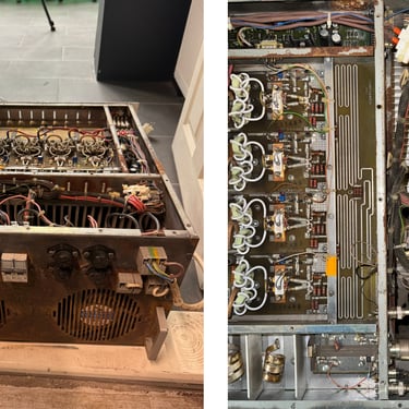
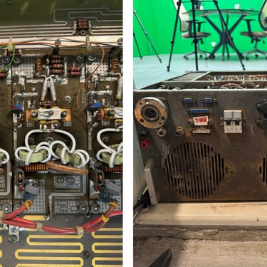
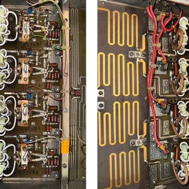
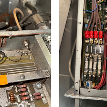
10. Example: 100-Watt RF Power Amplifier (FM Band)
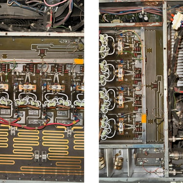
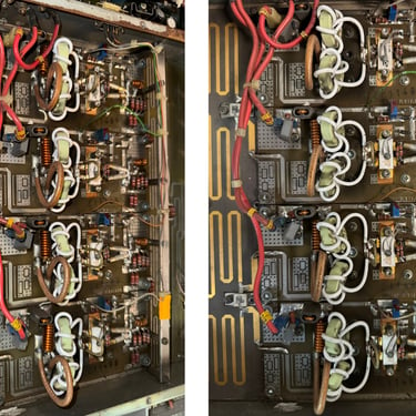
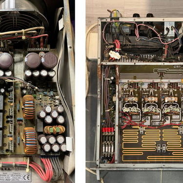
Below is a specification summary of a real-world medium-power RF amplifier used in FM broadcasting:
Frequency Range: 88 – 108 MHz
Gain: 40 dB
Input Power: 0.5 – 1 W
Output Power: 100 W
Device Used: BLF278 LDMOS transistor
Power Supply: 28V DC, 6A
Cooling: Forced-air cooled aluminum heatsink
Efficiency: >65%
Harmonics: <-60 dBc with low-pass filter
11. RF Amplifier Stages (Block Diagram)
plaintext
KopyalaDüzenle
Input Signal → Input Matching → Gain Stage (Transistor) → Output Matching → Output Signal
This basic layout is modified and expanded depending on power level, frequency, and linearity requirements.
12. Advancements in RF Amplifier Technology
Recent innovations are reshaping RF amplifier design:
GaN transistors have enabled smaller, more efficient, and more robust amplifiers.
Envelope tracking and Doherty architectures are used to increase efficiency in telecom systems.
Digital predistortion (DPD) is applied in modern PAs to linearize the output.
Integrated MMIC (Monolithic Microwave Integrated Circuits) simplify high-frequency designs.
13. Regulatory Considerations
RF amplifiers must comply with international standards:
FCC Part 15 / 73 (USA)
ETSI EN 302 (Europe)
ITU-R guidelines on spurious emissions
RoHS and CE compliance for environmental safety
Failure to comply can result in interference or legal penalties.
14. Conclusion
RF power amplifiers are a cornerstone of all RF communication systems. Designing an efficient, stable, and clean RF amplifier requires expertise in high-frequency electronics, thermal dynamics, impedance matching, and regulatory compliance. Whether it's a small LNA for a GPS receiver or a 10 kW FM broadcast transmitter, the principles remain fundamentally the same.
Modern tools and semiconductor technologies such as GaN and LDMOS have drastically improved the power handling, linearity, and compactness of RF amplifier systems, paving the way for higher data rates and more reliable communications.
