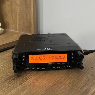
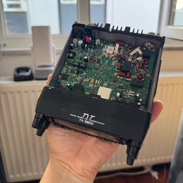
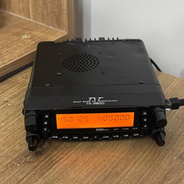
TYT TH-9800 – Ultra-Technical Overview
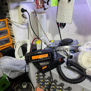
The TYT TH-9800 (and its “Plus” revision) is a quad-band mobile transceiver designed for amateur radio operators who require coverage across HF, VHF, and UHF segments within a single platform. Its architecture supports simultaneous reception on two bands and high-power transmission on four primary amateur bands.
AYBERK BLOG
TYT TH-9800 – Ultra-Technical Overview
The TYT TH-9800 (and its “Plus” revision) is a quad-band mobile transceiver designed for amateur radio operators who require coverage across HF, VHF, and UHF segments within a single platform. Its architecture supports simultaneous reception on two bands and high-power transmission on four primary amateur bands.
Frequency Coverage
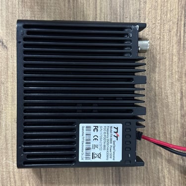
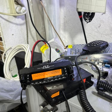
FunctionReceive (RX) RangeTransmit (TX) RangeWideband RX~26–33 MHz, 47–54 MHz, 108–180 MHz, 320–512 MHz, and in some versions 740–950 MHz—Amateur TX Bands—~26–33 MHz, 47–54 MHz, 134–174 MHz, 400–480 MHz
Native ham bands: 29 MHz (10 m), 50 MHz (6 m), 144 MHz (2 m), and 430 MHz (70 cm).
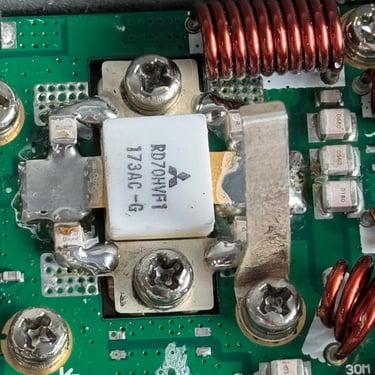
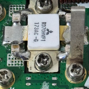
Transmitter Output Power
29/50/144 MHz bands: up to 50 W
430 MHz band: up to 40 W
User-selectable low/mid/high settings allow output between 5 W and 50 W (or 40 W on UHF).
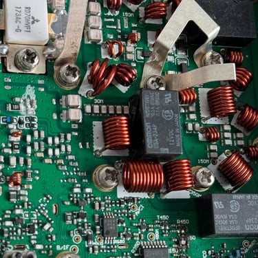
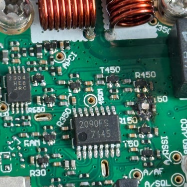
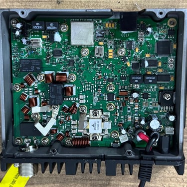
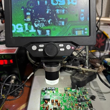
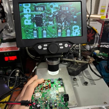
Receiver Architecture & Performance
Topology: Dual-conversion superheterodyne
Intermediate Frequencies: ~49.95 MHz / 450 kHz (left band), 38.85 MHz / 450 kHz (right band)
Sensitivity: ≤ 0.2 µV for 12 dB SINAD
Squelch threshold: ≤ 0.16 µV
Selectivity: ~12 kHz / 30 kHz @ –6 dB / –60 dB
Narrow/Wide FM modes supported for adjacent-channel rejection.
Functional Highlights
Dual VFO / Dual RX: Independent A/B bands, combinations: V+V, V+U, U+U
Full Duplex between VHF and UHF
Cross-Band Repeat: Enables use as a field repeater
Tone Signalling: CTCSS (≈50 codes), DCS (≈1024), DTMF, 2-tone, 5-tone.
Memory & Stability
Memory: ~809 programmable channels
Channel step: 2.5 / 5 / 6.25 / 7.5 / 8.33 / 10 / 12.5 / 15 / 25 / 30 / 50 / 100 kHz
Frequency stability: ±5 ppm (–10 °C to +60 °C).
Electrical Characteristics
Supply voltage: 13.8 V DC (nominal)
Current draw: ~0.5 A on standby RX; 8–8.5 A at 50 W TX
Operating temperature: –20 °C to +60 °C.
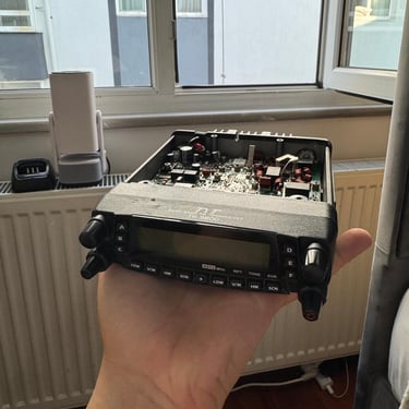
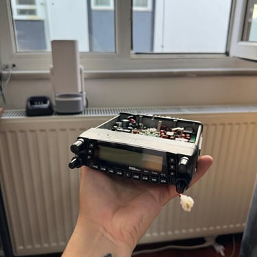
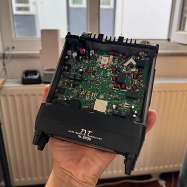
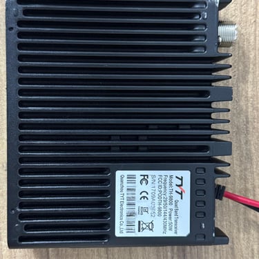
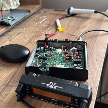
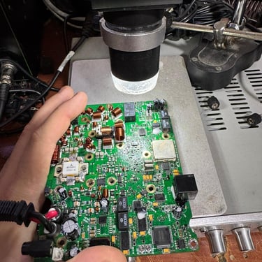
Mechanical Parameters
Dimensions: ~140 × 41.5 × 168 mm
Weight: ~1.2 kg
Antenna impedance: 50 Ω (internal duplexer).
Audio & Modulation
AF output: ~2 W @ 8 Ω (≤ 5 % THD)
Modulation distortion: < 3 %
Spurious/harmonic suppression: typically < –60 dB (–50 dB worst case at 29 MHz).
Lab-Style Measurement Data
ParameterValueNotesSensitivity (12 dB SINAD)≤ 0.2 µVGood weak-signal performanceSquelch opening≤ 0.16 µVSelectivity12 kHz (–6 dB) / 30 kHz (–60 dB)TX distortion< 3 %TX current @ full power~8 A (UHF) / 8.5 A (VHF/HF)Audio response300 Hz–3 kHz flat, roll-off beyond
Expected Frequency Response & Spectral Behavior
Passband shape: Roll-off at the –3 dB points for narrow/wide modes.
Adjacent-channel rejection: ~–60 dB.
AF response: Flat between 300 Hz and 3 kHz.
Harmonics/spurious: 2nd/3rd harmonics below –60 dB under nominal conditions.
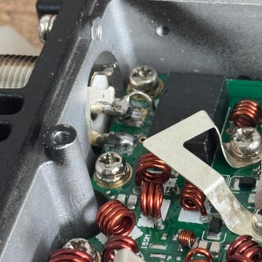
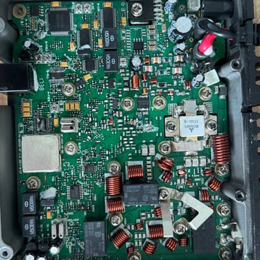
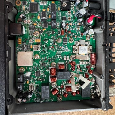
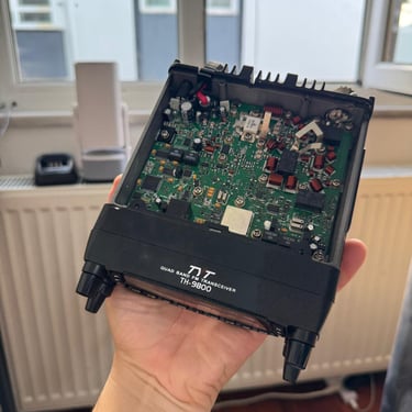
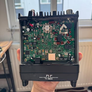
Engineering Notes
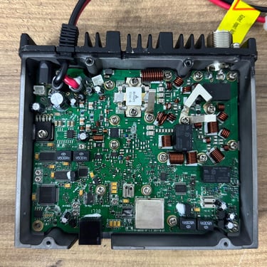
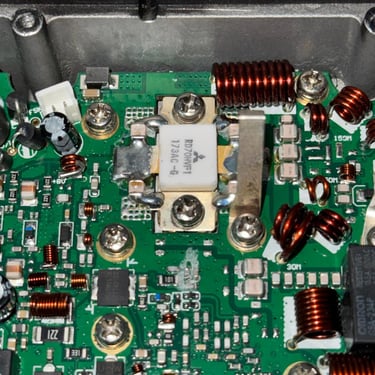
High RF output requires adequate heat dissipation; the transceiver’s chassis doubles as a heat sink.
Power cabling should support ≥10 A continuous draw with inline fusing.
Antenna system must handle >50 W and maintain <1.5:1 VSWR to protect the PA stage.
Performance degrades if supply voltage dips below ~11 V during high-power TX.
Technical Advantages
Wide multi-band coverage in a single chassis
Excellent flexibility (dual RX, cross-band repeat)
Competitive RF power for a compact mobile set
Solid audio and modulation fidelity.
Limitations
Compliance with local spectrum regulations is essential (10 m and 6 m TX may be restricted).
Harmonics increase slightly on 29 MHz at max power.
Not intended for continuous duty at full output without adequate ventilation.